Mobile Robot can use GPS device to acquire its global position, especially for long trip Robot. GPS will tell position (latitude, longitude, altitude, speed over ground, etc) that can be transmitted by the robot to other system or to be used as input data for decision making.
This Robot consist of:
1. Robot platform
2. 2 DC motors
3. GPS Starter Kit
4. Controller using MCS-51 microcontroller
5. Wireless data transceiver YS1020UA
6. Dry cell 6V
7. Motor driver
The Robot will report its coordinate position wirelessly based on GPS information. Program/code is done by Bascom 8051 .
:.
Cool projects of embedded system, submitted monthly. Explore topics & blog archieve.
Topics
- About mikron123 (1)
- Robotics (6)
- Temperature Control (1)
Custom Search
Saturday, January 31, 2009
Tuesday, December 30, 2008
Robot Motion Follower with Image Processing
Another idea for a motion following robot. This Robot brings a wireless camera to transmit real time video data to a computer. The computer is programmed with an image processing algorithm that detect the direction/motion of captured object. It will then command the robot to move to follow the object whereever it goes.
This Robot consist of:
1. Circular plate chassis
2. 2 servo motors
3. 2 plastic tyres and 1 ball caster
4. Controller using AVR microcontroller
5. Wireless camera
6. Wireless data transceiver YS1020UA
7. Mobile phone/GSM modem SIM300C
8. Batery pack 6V
The image processing algorithm developed by matlab and compiled to C++. The microcontroller program developed using Code Vision AVR.
Friday, October 31, 2008
Introducing Boe Bot Crawler to Junior High School Students
Parallax Boe Bot Crawler might be one of the most simple legged robot. It uses only 2 motor servo and moves forward, backward, turn left or right, only by controlling run/stop of the servos with a very simple programming. So, we consider this is a good start to introduce a type of legged robot to elementary/junior high school students in Indonesia.
This Parallax kit consist of:
1. Boe bot chassis (default with wheels)
2. Crawler kit
3. Two motor servos
4. Basic stamp micro education board
5. Some sensors (infrared, whiskler)
6. USB cable programming
7. Education book (very comprehensive)
8. CD software (BS compiler & downloader)
This kind of legged robot is introduced after our lesson about wheel robots. The crawler movement is like... grasshopper (funny enough). The children like to assemble and playing around (with a simple programming of course).
Although it's design has some limitations, but we think it is good enough as a start before understanding other complicated structure/movement of legged robot such as "real hexabot".
Sunday, September 28, 2008
Fire Fighting Robot
This is a popular type of robot in many contest, a Fire Fighting Robot! The purpose is to find the fire/candle, blow it off, and sometime also have to find/rescue the baby. The field area consists of many rooms, stairs and sometime with many obstacles.
The main parts of this robot are:
1. Plate chassis from aluminium
2. 3 servo DC motors (1 for turret)
3. Wheels: 2 active & 1 passive
4. Controller using ATMega microcontroller
5. Some Ping ultrasonic ranging sensors
6. UVTron flame sensor
7. Devantech Magnetic Compass
8. Brushless Fan turret to blow the fire/candle
9. Batery pack 6V
The robot activated by sound/switch from home location. It senses fire/flame direction then search the room where the candle is placed. It will blow the fire and back to home location. The program done in C using CodeVision AVR.
Saturday, August 30, 2008
Tank Robot Controlled By Mobile Phone
Another mobile robot! A tank robot which is activated, controlled, and report to a mobile phone. The communication can use direct CSD (Circuit Switch Data) and SMS (Short Message Service). In the next step, it will also use video call. So, remote controlling can be done in very long distance and more sophisticated way.
The main parts of this robot are:
1. Chassis from tamiya tank
2. 2 DC motors
3. DC motor driver using H-bridge
4. Controller using AT89S51 microcontroller
5. Ping ultrasonic ranging sensor
6. SHT11 temperature & humidity sensor
7. Mobile phone/GSM modem SIM300C
8. Batery pack 6V
This robot activated and deactivated via SMS command. It use its ranging sensor to adjust movement. Real time data of temperature and humidity and also some other report are sent to user via SMS or CSD. The program done in Basic using Bascom8051.
Saturday, July 5, 2008
Robot with Wireless Color Camera
Need a spy robot that give your laptop an eye and information about remote environment condition? You also will need to control and get those all data wirelessly. This is a project about that.
The main parts of this robot are:
1. Chassis from remote control car toy (4WD)
2. 2 DC motors for wheel
3. DC motor driver using H-bridge
4. 1 mini stepper motor to rotate camera
5. Stepper motor driver using 2803
6. Controller using ATTiny2313 microcontroller
7. Wireless color camera
8. Transceiver 433 MHz
9. Radio AV Receiver
10. Batery pack 9V
This robot get real time view from wireless camera, and controlled via laptop . The control actions include moving forward, backward, turn left, turn right, rotate camera (cw and ccw) . The distance between robot and control station (laptop) depend on the max distance of tranceiver which is 100 m in this project. The program done in C using CodeVision AVR for microcontroller and Visual Basic for user interface in laptop.
Thursday, July 3, 2008
Legged Robot Hexapod
This is a project to make six leg robot (hexapod bot). Legged Robot has higher difficulty level of design and programming than wheel robot. Hexapod bot imitate the structure and movement of insects.
The main parts of hexapod bot are:
1. Chassis
2. 12 servo motor 180 degree (2 servo/leg)
3. Controller based on AVR 8535 microcontroller
4. Battery pack 6V DC.
Beside that, range sensors such as ultrasonic or infra red could be attached to the robot to have more sophisticated function of robot in the real application.
In this project, the hexapod bot do a simple maneuver/movement, moving forward, turn left, turn right .
The program done by C language using Code Vision AVR.
Sunday, June 29, 2008
Temperature Control for Incubator
This is a project to make a working prototype of baby incubator in miniature scale. It will keep the warm temperature based on settings defined by user/operator (minimum & maximum temperature) . The same concept can be applied to other similar project, such as room controlled temperature etc.
The main part of this mini incubator:
1. Electric heater 12 V
2. Fan 12 V, to make air in/out from incubator
3. Temperature sensors, LM35/PTC/NTC/termocouple
4. Controller based on microcontroller AT89S51
5. ADC 8 channel, using 0809
6. Transistor/relay for controlling heater
6. LCD display 2x16, for user setting
7. Matrix keypad 4x3, for user setting
If temperature under the minimum threshold (set by user/operator), the controller will turn on the heater. It will keep heating until temperature reach the maximum threshold. If temperature above the maximum threshold, the controller will turn on the fan to make fresh cold air enter the incubator. And so on. The program done by assembly language.
Schematic download:
http://prasimax.googlepages.com/incubator_sch.jpg
Source code download:
http://prasimax.googlepages.com/incubator.asm
(note: you may need to change formula in program acoording to your sensor calibration)
Friday, June 27, 2008
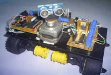
Wheel Robot with Ranging Sensor
Do you usually take a walk in the morning with your dog beside you? Do you want something cool? What about a robot follow behind you?
This is a project about Robot that have four wheel (4WD) that have capability to response based on ultrasonic ranging sensor.
That main parts of the robot are:
1. Wheel, motor and chasis, taken from 2 Tamiya toys
2. Robot controller based on microcontroller AT89S52
3. Parallax PING ultrasonic ranging sensor
4. Stepper motor to rotate "the ultrasonic eye"
5. Stepper motor driver based on 2803A
6. DC motor driver based on L293
Robot will try to find object in 30 cm. The robot then will follow (keep the 30 cm distance) to the first object found. So if I give my hand close to the robot than it will move based on the position of my hand (as long as I move my hand slowly).
The program done by assembly language.
Thursday, June 26, 2008
The Blogging is Starting
Mikron123 is website and blog name, made by embedded system and science engineering hobbyst. This blog is intended for sharing our activity to the world, so that everyone that have the same interest can also share with us.
Named mikron because the projects mainly based on microprocessors or microcontrollers... and the number 123 means that our projects is for (and may be from) beginners. We try to make the project in the easiest way and keep it simple.
So, have fun !
Subscribe to:
Posts (Atom)
Other Projects
- About mikron123 (1)
- Robotics (6)
- Temperature Control (1)
Custom Search